NOTES
Some minor changes have been made since the first one built.
The values of R1 and R2 have been changed from 8k2 to 10k
Q21 has been changed from 2N3904 to ZTX450
Q22 has been changed from 2N3906 to ZTX550
The change of these two transistors was solely to make them easier to glue together, as the final pin out is a tidier fit. The 2N3904 and 2N3906 will work fine.
The 1N4001 on the relay has been replaced by a 1N4148.
The screen across the board on top of the FET to provide isolation between the inductors is no longer fitted.
I found that when fitted in the 847, the close proximity of the circuit board on one side and the metal screen on the other, detuned the coils.
As it is not possible to adjust them with the metal screen fully in place, I put a screen around L1. Adding a screen to L2 made very little difference.
Now they can be adjusted before fitting.
This made the other screen across the boards unnecessary.
(I found the commercial kit also detuned when fitting the screen back onto the 847)
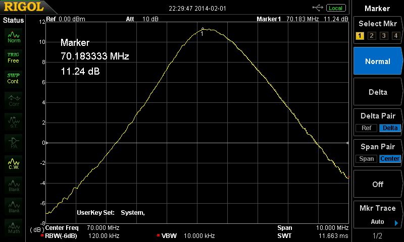
The resistors have been changed to 1/6W instead of 1/4W, and smaller capacitors fitted. This makes construction easier and neater, and gets rid of a blip in the response curve when in bypass mode.
The changes have resulted in a better response curve.

